This is default featured slide 1 title

Go to Blogger edit html and find these sentences.Now replace these sentences with your own descriptions.

This is default featured slide 2 title

Go to Blogger edit html and find these sentences.Now replace these sentences with your own descriptions.

This is default featured slide 3 title

Go to Blogger edit html and find these sentences.Now replace these sentences with your own descriptions.

This is default featured slide 4 title

Go to Blogger edit html and find these sentences.Now replace these sentences with your own descriptions.

This is default featured slide 5 title

Go to Blogger edit html and find these sentences.Now replace these sentences with your own descriptions.

Friday 30 March 2018

Capacity Support Telapak Foundation

Capacity Support
Telapak Foundation


A. Types of Foundation Crashes

• To study soil behavior at the beginning of loading until it reaches the collapse, an overview of a rigid foundation at the bottom of foundation foundations that is no more than the width of its foundation. The addition of the foundation load is done gradually.

Phase I, at the beginning of the load application, the soil under the descending foundation followed by the deformation of the soil leterally and vertically downward. As far as the applied load is relatively small, the decrease is proportional to the applied load (in an elastic balanced state). The soil is compressed, raising its support capacity.
Phase II, The addition of subsequent loads, soil wedges will form at the foundation base and deformation of dominant land plots. The plastic ground movement starts from the edge of the foundation, and as the plastic load increases, the leteral motion of the soil becomes more apparent, followed by local fractures and friction on the soil around the edges of the foundation.
Phase III, the deformation velocity increases with increasing load. Deformation is followed by movement of the soil outward so that the ground is swollen at the surface, then the foundation soil is collapsed. The field of collapse is in the form of an arch and a line, called the radial shear plane and the linear sliding field.

Kapasitas Dukung Fondasi Telapak

Kapasitas Dukung


Fondasi Telapak

A. Tipe Keruntuhan Fondasi


•        Untuk mempelajari perilaku tanah pada saat permulaan pembebanan sampai mencapai keruntuhan , dilakukan tinjauan terhadap suatu fondasi kaku pada kedalaman dasar fondasi yang tidak lebih dari lebar  fondasinya. Penambahan beban fondasi dilakukan berangsur-angsur.

       •Fase I, saat awal penerapan beban, tanah dibawah fondasi turun yang diikuti oleh deformasi tanah secara leteral dan vertikal ke bawah. Sejauh beban yang diterapkan relatif kecil, penurunan sebanding  dengan beban yang diterapkan (dalam keadaan seimbang elastis).  Tanah mengalami kompresi, sehingga menaikan kapasitas dukungnya.


Fase II, Penambahan beban selanjutnya,baji tanah akan terbentuk di dasar fondasi dan deformasi plastis tanah dominan. Gerakan tanah plastis dimulai dari tepi fondasi, dan dengan bertambahnya beban zona plastis akan berkembang, gerakan leteral tanah semakin nyata diikuti dengan retakan lokal dan gesekan pada tanah sekeliling tepi fondasinya.

Fase III,  kecepatan deformasi semakin bertambah seiring dengan penambahan beban. Deformasi diikuti dengan pergerakan tanah ke arah luar sehingga tanah menggembung pada pemukaan, kemudian  tanah fondasi mengalami keruntuhan. Bidang runtuh  berbentuk lengkungan dan garis, yang disebut bidang geser radial dan bidang geser linier.


FOUNDATION DESIGNS


FOUNDATION DESIGNS
   A.    Preliminary
The foundation of the building is the most important construction in a building. Because the foundation serves as a barrier to all the loads (life and death) that are above it and style of force from the outside. The foundation is part of the structure that serves to continue the burden to the supporting ground layer below it. In any structure, the load occurring either due to the weight of itself or due to the load of the plan shall be channeled into a supporting layer in this case is the ground under the structure.
In the foundation there should be no decrease in the foundation of the foundation or even the uniform foundation over certain limits, namely:
1. General building 2.54 cm
2. Factory building 3.81 cm
3. Warehouse 5.08 cm
4. Engine foundation 0.05 cm
Many factors in the selection of the type of foundation, among others, planned load work, type of soil layer, and non-technical factors such as construction costs, and construction time. The type of foundation chosen should be able to guarantee the position of the structure of all working forces. In addition, the supporting ground must have sufficient carrying capacity to carry the work load so that no collapse occurs. In certain cases if it is not possible to use shallow foundations, deep foundations are used. The foundation in which is often used is pile foundation. According Bowles (1984), pile foundation is widely used in high-rise buildings that get lateral and axial loads. This type of foundation is also widely used in structures built on expanding soil (expansive soil). The carrying capacity of the pile obtained from the skin friction can be applied to withstand the uplift force that occurs. The erosion factor in the river is also a consideration of the use of piles on the bridge.
   B.     Count Analysis
Is known:       Cohesion and Angle of internal ground friction = 15 KN/m2& 25o
                       Soil type = Sand
                        Fc’ = 40 Mpa = 400 kg/cm2

                        Fy = 240 Mpa = 2400 kg/cm2


Figure 3.1 Pieces of Piles
Foundation Pole: 
1. In use diameter pole ø 40 cm, steel reinforcement 8 ø 16 m 
2. Area of concrete
Ac       = ¼.Ï€.d2
            = ¼. 3,14. 402                                 
            = 1256 cm2

   3.      The area of steel reinforcement

 As        = ¼.Ï€.d2. 8
            = ¼. 3,14. 1,62. 8
            = 16,077 cm2

   4.      Material capacity:

a.       Pr        = 0,85. f {0,85. fc’(Ac-As) + As.fy}
= 0,85. 0,7 {0,85.400(1256-16,077)+16,077.2400}
= 273794,3789 kg
= 273,794 ton
b.      f         = 0,7    for spiral stirrups

   5.     Capacity of land support:
        Example of a depth of 5 m (sand)
Qc       = 145 kg/cm2
Ft         = 274 kg/cm
Sf 1     = 3 ;Sf 2 = 5
K         = Ï€.d = 3,14 . 40 = 125,6 cm
Qa       = (Ap. qc)/SF1 + (k.ft)/SF2
= (1256  . 145) / 3 + (125,6. 274) / 5
            = 67589,54kg = 67,59 ton
Table 3.1 Soil Sondir Data
Depth
qc
Ft
Qa
M
kg/cm2
kg/cm'
Kg
0,00
0
0,00
0
0,20
10
10,00
4437,86
0,40
5
20,00
2595,73
0,60
10
24,00
4789,54
0,80
15
34,00
7134,08
1,00
40
54,00
18103,14
1,20
115
64,00
49754,34
1,40
90
84,00
39790,08
1,60
60
104,00
27732,48
1,80
35
114,00
17517,01
2,00
40
124,00
19861,54
2,20
20
128,00
11588,69
2,40
25
138,00
13933,22
2,60
25
148,00
14184,42
2,80
25
156,00
14385,38
3,00
25
166,00
14636,58
3,20
21
174,00
13162,88
3,40
25
184,00
15088,74
3,60
35
204,00
19777,81
3,80
150
224,00
68426,88
4,00
160
244,00
73115,94
4,20
180
264,00
81991,68
4,40
145
274,00
67589,54
4,60
120
294,00
57625,28
4,80
145
304,00
68343,14
5,00
45
324,00
26978,88
5,20
45
354,00
27732,48
5,40
45
364,00
27983,68
5,60
31
382,00
22574,50
5,80
25
392,00
20313,70
6,00
20
402,00
18471,57
6,20
15
422,00
16880,64
6,40
30
442,00
23663,04
6,60
25
452,00
21820,90
6,80
20
462,00
19978,77
7,00
30
466,00
24265,92
7,20
35
476,00
26610,45


Figure 3.2 Cut Pile Foundation and Pile Position

                             
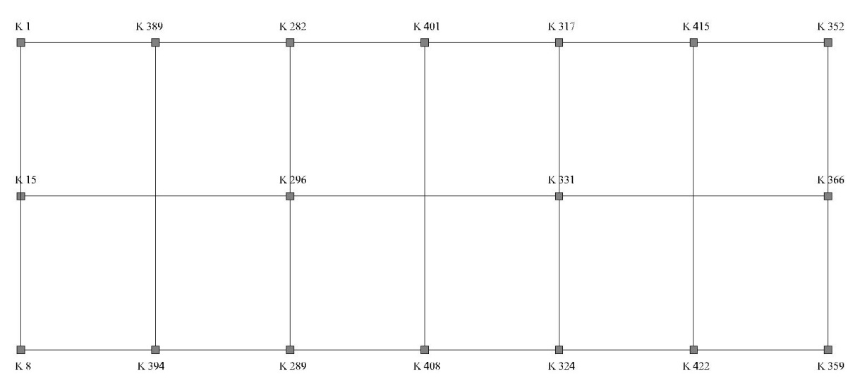
 Figure 3.3 Top View Foundation


   6.     Pile support capacity
  
                    a. Based on the load P = 202.06 tons
                    b. Based on land P = 67.59 tons  
                        So the support capacity of pole permit = 67.59 tons In use P permit = 67 tons
                    c. The result of structural analysis on the ground floor column  P = 2056,1 KN= 205.61 tons
                    d. Permit capacity P permit = 67 tons
                    e. Needs polen = P / Pijin = 205,61 / 67 = 3,069 used 4 pieces of pole 
                    f. Distance pole min 2D
    
   7. Load Control
·      In base column P = 205,61 ton and My = 198,9 KN = 19,89 ton
        Number of pole n = 4
                                               
                                                                                                                         <Pijin = 67 tons (fulfilling)

        With the capacity of the foundation license (P permit) at 4.4 m deep.

Table 3.2 Checking The foundation of each qualified column


Kolom
P kolom (ton)
P ijin (ton)
My (ton.m)
n
P1
P2
Keterangan
K1
139,91
58
16,40
4
40,41
40,41
Memenuhi
K15
153,05
58
18,61
4
43,04
43,04
Memenuhi
K 8
140,93
58
15,98
4
40,61
40,61
Memenuhi
K 387
155,72
58
13,72
4
43,57
43,57
Memenuhi
K 394
155,93
58
13,57
4
43,61
43,61
Memenuhi
K282
156,56
58
11,78
4
43,74
43,74
Memenuhi
K296
205,61
58
13,63
4
53,55
53,55
Memenuhi
K289
156,35
58
11,86
4
43,70
43,70
Memenuhi
K401
150,55
58
19,89
4
42,54
42,54
Memenuhi
K408
150,30
58
10,19
4
42,49
42,49
Memenuhi
K317
148,99
58
19,13
4
42,22
42,22
Memenuhi
K331
200,13
58
10,62
4
52,45
52,45
Memenuhi
K324
150,41
58
9,30
4
42,51
42,51
Memenuhi
K415
147,65
58
11,19
4
41,96
41,96
Memenuhi
K422
165,42
58
11,40
4
45,52
45,52
Memenuhi
K352
126,37
58
11,41
4
37,71
37,71
Memenuhi
K366
202,06
58
13,16
4
52,84
52,84
Memenuhi
K359
175,71
58
11,10
4
47,57
47,57
Memenuhi

Contact Form

Name

Email *

Message *